My newest project; LED Display.
Youtube video of it
The idea came from germany, where the group “CCC” or Chaos Computer Club, created a matrix of lights in the “Haus des Lehrers” building at Alexanderplatz in Berlin. They installed computer controlled lights in 144 windows spanned over 8 floors (18 windows per floor). This was done first in 2001. You can look at their webpage at BlinkenLights.de.
If you search for Blinkenlights on video.google.com or youtube you will find a really interesting documentary about the Blinkenlights project. I saw this video a few years ago, but when I saw it again now recently, I ignited on all my sparks. I had to make my own small scale version.
So I surfed the web, and I found, amongst others, BlinkenLEDs. These guys had done almost exactly what I wanted to do. I saw that they were using a 4094 Bit-shift register. I myself would have used a 74xxx series chip, but since they had done it perfectly with this chip, and since it looked like it worked perfectly even without resistors for each LED, I incorporated the 4094 chip in my plans.
My plan differs from theirs in two ways. I wanted mine to be able to run without a computer connected. For this I planned using the PIC16F628. Someone might wonder why I wouldn’t use the cheaper “less cmos” version PIC16F84. But the answer is also the answer to the other way my project differs. I wanted to use the serial port, instead of the LPT(read: printer) port. And the PIC16F628 has hardware USART capability, which makes RS232 connection simple.
The part-list for mye circuit is as follows:
  1     PIC16F628
  1     18-PIN socket (for the PIC)
  1     MAX232
  1     95128 SPI controlled EEPROM (128KB memory)
  1     20MHz Crystal for the PIC
  1     33uF electrolyte capacitor (noise reduction for PIC)
  2     22pF capacitors for 20Mhz crystal
  2     Veroboards (prototyping boards)
  3M    Flat cable
  4     1uF electrolyte capacitors (for the MAX232)
  18    4094 Bit shift registers
  144   Red 3mm Leds (I've got 4000 spare :P)
misc Wires |
1 PIC16F628
1 18-PIN socket (for the PIC)
1 MAX232
1 95128 SPI controlled EEPROM (128KB memory)
1 20MHz Crystal for the PIC
1 33uF electrolyte capacitor (noise reduction for PIC)
2 22pF capacitors for 20Mhz crystal
2 Veroboards (prototyping boards)
3M Flat cable
4 1uF electrolyte capacitors (for the MAX232)
18 4094 Bit shift registers
144 Red 3mm Leds (I've got 4000 spare :P)
misc Wires
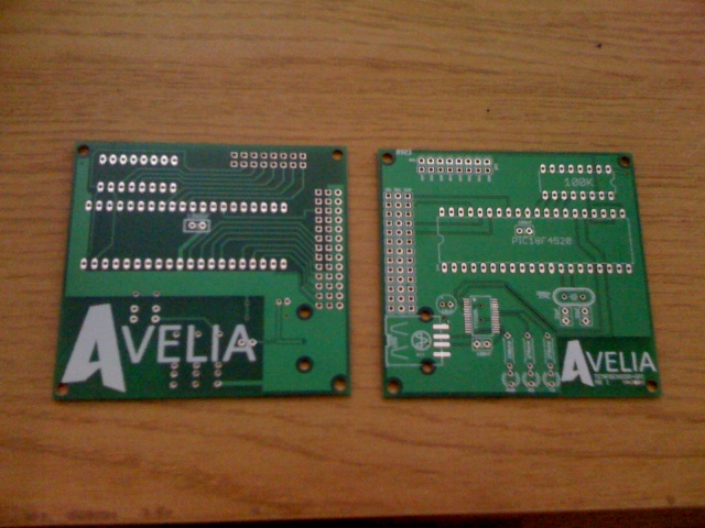
The circuit was planned live inside my head ;) I have regretted this a bit as the project evolved, but all in all, I’m pretty happy/proud about the result.
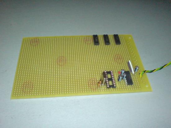
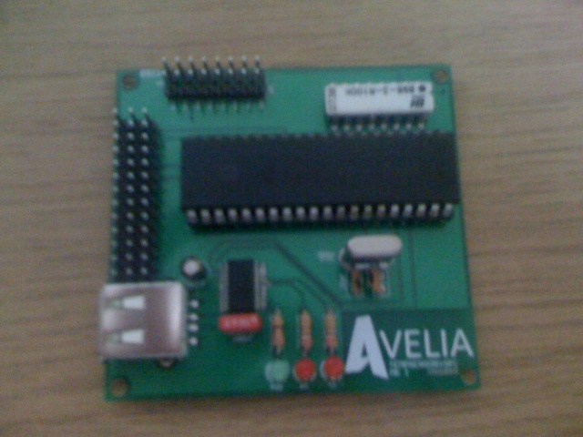
Here you can see a picture of the controller-card when I had completed the wiring of 3 bit-shift registers, the PIC16F628 and the MAX232. I were planning on having two rows of bitshift registers filling the whole left side of the board, spacing just enough to have 8 wires up to the LED board from each register.
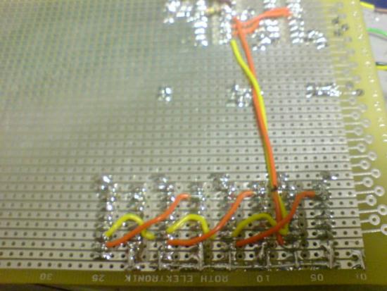
Here you see how I wired the first 4 bit-shift registers. I found out later, that I wanted the first register to be on the next row. Even though here you can see that I have connected the first register on this “second row” to the PIC16F628 processor. If you are really observant, you can tell that I have changed my mind a few times on the wiring of the bottommost row ;P
It also prooved later that I should have thought it over just one more time. Because here lies the root of all evil! I wired up all the STROBE pins to +5v, and wired together all the OUTPUT ENABLE pins, to one of the ports of the PIC processor. This was not what I meant to do. Because of this, my display will flicker a bit each time it updates the screen. But since it is a 20MHz processor, it’s hardly noticable.
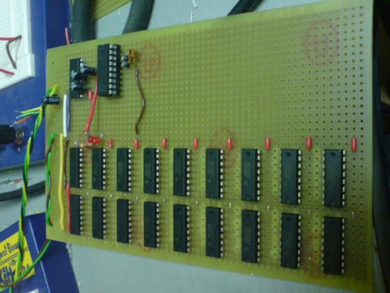
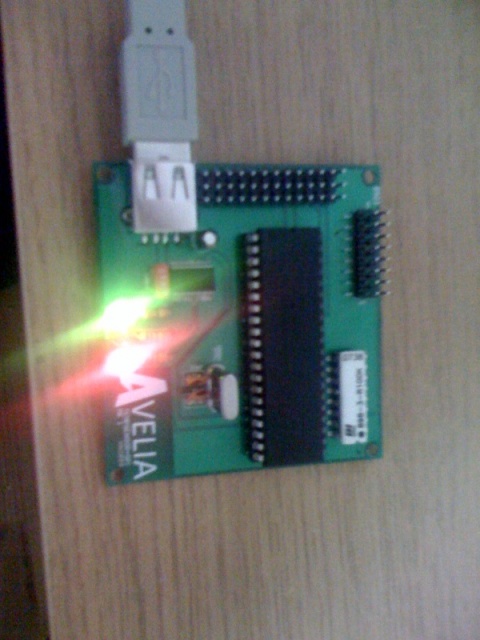
This is a picture of all the 18 Bit-shift registers wired up.
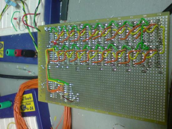
This is all the registers wired up. You can see I have moved the control-cable from the processor to the leftmost registers. I tested the circuit with a program on the processor that lit one row by one, and all of them worked at the first try! :D
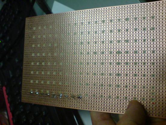
It was then over to the LED card. Here I have drilled out 144 holes. Pretty boring work I can tell you…. You see that I have wired the ground from the 9 first LEDs.
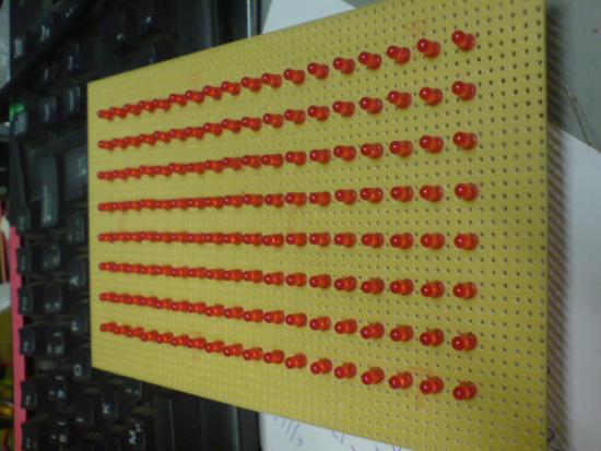
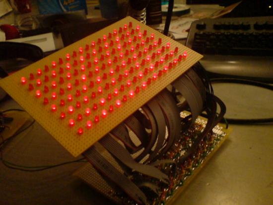
This is how it looks when all 144 LEDs are connected. This took very long time, especially afther the first few rows. Since my friend had to leave, and so I was two hands short. But I got it done at the end. I wish this board was pre-tinned like the controller-vero board, since this made it even harder to solder the LEDS with only my own two hands.
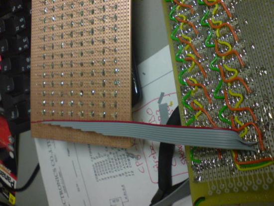
Then I started wiring up the leds to the shift registers. I am glad that I saw how terrible the wiring looked at the projects at BlinkenLEDS. So that I bought flat cable for my project. I’m pretty satisfied with how I wired up the leds to the flat cable. Even though it took quite a long time. After each new row, I powered up the circuit to check if there were any “dead pixels”. There were a few (read: totally 4-5), mostly since the board wasn’t pre-tinned, and I don’t have flux other than what the tin provided. But since I was in lack of hands, the flux evaporated before I got to actually solder the leds to the board.
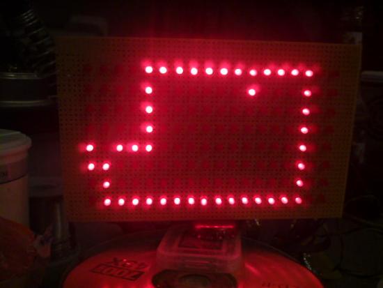
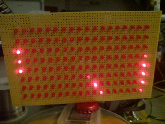
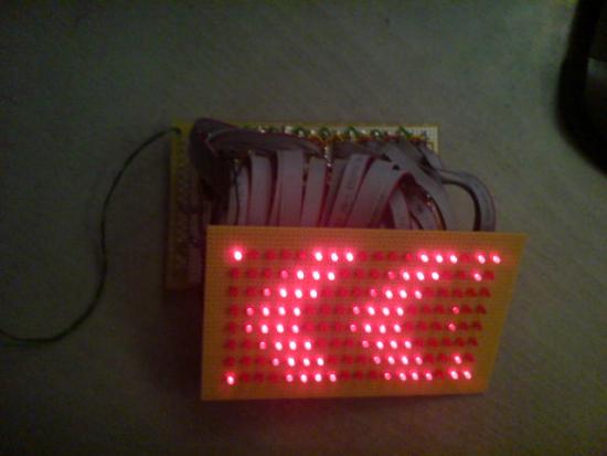
Here you see the board running a program that alternates between all the leds. The display works! It was time for celebration with a “blm” movie from the BlinkenLights project. So I wrote a parser in perl that converted a .blm file to .c code for my PIC16F628.
#!/usr/bin/perl
use strict;

my $ttl=100;
my @arr;
my @outarr;
my $out;

while(<>) {
  if (m/^@(\d+)$/) {
    $ttl = $1;
  }
  if (m/^[01]{18}$/) {
    push @arr, $_;
  }
  if (scalar(@arr) == 8) {
    print " PORTB &= ~SHOW; // Hide display\n";
    for my $pos (0..17) {
      for my $ari (0..7) {
        push @outarr, substr($arr[$ari],$pos,1);
      }
      print " sendbyte(0b".join("",@outarr).");\n";
      @outarr = ();
    }
    @arr = ();
    print " PORTB |= SHOW; // Show display\n";
    print " delay_ms($ttl);\n\n";
  }
} |
#!/usr/bin/perl
use strict;
my $ttl=100;
my @arr;
my @outarr;
my $out;
while(<>) {
if (m/^@(\d+)$/) {
$ttl = $1;
}
if (m/^[01]{18}$/) {
push @arr, $_;
}
if (scalar(@arr) == 8) {
print " PORTB &= ~SHOW; // Hide display\n";
for my $pos (0..17) {
for my $ari (0..7) {
push @outarr, substr($arr[$ari],$pos,1);
}
print " sendbyte(0b".join("",@outarr).");\n";
@outarr = ();
}
@arr = ();
print " PORTB |= SHOW; // Show display\n";
print " delay_ms($ttl);\n\n";
}
}
The result was a moving version of this:
Source of the BLM file, and moving GIF of the animation can be found here.
I have now coded the RS232 support and I first modified the above code to send the animation directly to the display. And then I coded myself a perl module to control the display live. I called it “Acme::LEDDisplay” and using some quick hacks. I have support for pset (pixel set), pget (pixel get), line, circle and text.
With this I can create live output from just about everything. The sky is the limit :D
Here is a video sample of “spin.blm” on my display: MOV00315.avi
The project is almost done. I have made it possible to send blm movies directly from the PC, and control the display in simple perlcode. But the “offline-playing” part is not done. I had a few problems getting the SPI<->EEPROM communication to work, so I have ordered some more EEPROMs to check if the one I have is broken. I really hope that, because it would be fun to be able to upload a few “movies”, and let it run for itself on batterypower. Maybe show off a few christmas greetings for example ;)
I also might wire it to my recently bougt Bluetooth module, so I can control it without any wires whatsoever :)
If you want more info about how I wired things up, sourcecode, etc. Give me a reply!